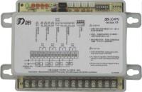
DEI-304PN-Dei Vietanm-Stc Vietnam
Nhà cung cấp: STC VietNam
 Mr. Văn Tú
| ‧Parameters must be set via DEI-950 software. | ||||
| ‧Communication Form:Modbus-RTU | ||||
| ‧Communication Interface:RS- 485 | ||||
| ‧IP available to set:1~63 | ||||
| ‧IP is detected only once when power is supplied, and it will detect the changed IP only when power is supplied again. | ||||
| ‧Output capacity:Do1~Do4,10A/250VAC / C contact X4 , resistance load | ||||
| ‧Communication / Power indicators(Green color):It remained green after power is supplied, and blinking when receiving communication. | ||||
| ‧Output contact indicator ( Red ):Do1~Do4 LED x4 coressponding to the act of Do1~Do4 | ||||
|
‧PCB protection: when the sensor on PCB is failed or its temperature ≧65℃, controller will switch off all output contacts compulsively to ensure safety. |
||||
|
‧Power failure memory: all parameters will be stored in memory of CPU. CPU will activate with parameters after power is supplied or power re-supplied when there is a power failure occured. |
||||