|
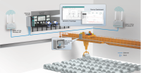
The Ircon ScanIR II Line Scanning Infrared Thermometer bridges the gap between spot temperature measurement and thermal imaging. Well suited for temperature measurement of moving processes such as webs, sheets, rolls, and films, the ScanIR II Line Scanner can be run stand alone or with Ircon interface software.
-
Provides easy-to-understand temperature map of your process
-
Rugged line scanning sensor for industrial applications
-
Fast 10, 25, 50 or 100 Hz Scan Rates
-
500 or 5000 Samples Per Scanline
-
Accurate to within 0.5% of reading
-
Profile, 2D and 3D Images of process temperatures
-
Spot, Zone, or Spot Auto-Track Modes
-
Digital or Analog Outputs of Ten Spot or Zone Temperatures
-
Operator interface simultaneously displays two sensors in real time
-
ActiveX® Controls
-
Laser aiming option
Basic System Includes:
Temperature Sensor, Power Supply/Processor, Power Supply Cable, and Ethernet Cable with Connectors.
System Options:
Internal Laser Aiming System, Analog Output Cards, Operator Interface PC, and four different Operator Interface
Software packages.
Installation Accessories:
Quick Release Mount, Water Cooled Enclosure, Air Purge/Cooler Air Blower, Hose, with associated Connection Hardware, and Pneumatically Operated Shutter. Only ScanIR II Offers These Features….
Stand Alone Capability….
-
Temperature Sensor and Power Supply/Processor are a Stand Alone System
-
PC is not required for temperature calculation
-
PC is not required for Analog or Digital Outputs
Powerful Temperature Images….
-
Make your process temperatures easy to understand
-
Helps operators improve product quality and save energy
-
Can vastly help to reduce setup and changeover times thereby reducing scrap
-
Software palette displays 50 colors simultaneously provides better image resolution
Fast & Accurate….
-
During each 90° scan, the ScanIR II Line Scanner makes from 500 to 5000 measurements (model dependent)
-
10, 25, 50 or 100 Hz Scan Rate models
-
Accurate within 0.5% of reading
-
Optical Resolutions up to D/300 (Optical Spot Size is distance divided by 300)
-
Optional Built-in Visible Laser projects line on target to aid in aiming sensor
-
Capable of detecting small temperature differentials
-
All Spots or Zones are calibrated against a common reference point
Flexible Processing Capability ….
-
Sensor/Processor can operate in the Spot, Zone, or Spot Auto-Tracking Modes
-
User can Define up to 10 Spots (lanes) or 10 Zones (rectangular or parallelogram areas)
-
Spot and Zone temperature size and location are user definable
-
Spots or Zones temperature can overlap each other if needed
-
Individual High and Low Setpoints for each Spot or Zone temperature
-
Individual Peak Picker for each Spot
-
Each Spot or Zone temperature can have individual Analog Output
-
Variety of Image and Data Archiving Capabilities
-
Each spot or zone area provides max, min, or average temperature within the area
Variety of Operator Interface Software Packages Available….
-
Ircon ScanIR II, SpotMaster Software (typically for continuous processes)
-
Ircon ScanIR II, ZoneMaster Software (typically for intermittent or piece processes)
-
Ircon ScanIR II, Float Glass Profiler Software (For glass annealing)
-
Ircon ScanIR II, Configurator Software (to configure system for Spot Mode when imaging, etc. is not required)
Easy To Configure….
-
Remote Focusing via software command
-
Easy to operate Windows NT®/2000® Based software
-
Software provides real-time temperature Imaging
-
Saved Recipes can be easily loaded for quick configuration of Sensor and Operator Interface PC
Easy To Install and Maintain….
-
Quick-Repeatable Mounting accessory
-
Optional Water Cooled Enclosure
-
Optional Air Purge
-
Optional Manually or Automatically Operated Shutter for installation on furnaces and lehrs
-
Rugged Mineral Window assembly is easily replaced
-
Only one Quick Disconnect Cable connected to sensor
-
Temperature Sensor to power Supply Cable can be up to 153 to 305-m (500 or 1000-ft.) long (model dependant)
-
Ethernet Cable can be up to 305-m (1000-ft.) long (or longer), (from Power Supply/Processor to PC)
Specifications:
Temperature Sensor:
Scan Angle: 90° (adjustable)
Scan Rate: 10, 25, 50, or 100 Hz
System Response Time: (At Analog Output)
@ 10 Hz, 0.100 to 60 Seconds
@ 25 Hz, 0.040 to 60 Seconds
@ 50 Hz, 0.020 to 60 Seconds
@ 100 Hz, 0.010 to 60 Seconds
Calibration Accuracy: ± 0.5 % Reading or 6°F (3°C)
Repeatability: Within 0.3% of Reading or 2 degrees
Remote Focus: 610-mm (24") to infinity
Spectral Regions:
1.0µ
1.5 to 1.6µ
2.1 to 2.4µ
3.2 to 3.5µ
4.4 to 5.1µ
Remote Focus: 610 mm (24") to infinity
Spot Size:
Optical Resolution Element (ORE) = D/F
(Depending on Model)
F = 50
F = 75
F = 100
F = 150
F = 200
F = 300
Scan Position Accuracy: ±5 mrad
Detector Alignment Accuracy to Laser: ±6 mrad
Signal Conditioning Filters:
-
Maximum/Average/Minimum Spot or Zone Temperatures
-
Peak Picker (Spot Mode) with adjustable decay rate 0 to 550°C (0 to 1000°F) per second;) receives input from (Spot Mode) filter
Ambient Temperature Range:
-
32 to 130°F (0 to 55°C) without cooling
-
32 to 212°F (0 to 100°C) with Cooling Enclosure and Water Cooled Faceplate
Temperature Sensor Humidity: Limit 10 to 90% non-condensing
Vibration: IEC-68-2-6
Shock: IEC-68-2-27
Enclosure: Designed to meet NEMA 12K and IP52 standards
Optional Laser: Class II laser product per IEC 825-1 (1997) and CDRH 21 CFR 1040
Temperature Sensor Dimensions: (W x H x L) 243 x 233 x 342 mm (9.56 x 9.16 x13.49")
Temperature Sensor Weight: 10 kg (22 lbs.)
Modes of Operation:
Spot Mode (10 Max)
Zone Mode (10 Max)
Spot Auto-Tracking (5 Max Temperature outputs, plus target width information)
Focusing: Remote via Operator Interface
Power Requirements: Auto Switching 100-240 Vac, 50/60 Hz; 230 VA
Processor/Power Supply Dimensions: (W x H x D) 380 x 380 x 210 mm (14.96. x 14.96 x 8.27)
Processor/Power Supply Weight: 11.4 kg (25 lbs.)
Processor/Power Supply Ambient Temperature Rating: 0 to 55°C (32 to 130°F)
Processor/Power Supply Vibration: IEC-68-2-6
Processor/Power Supply Shock: IEC-68-2-27
Processor/Power Supply Humidity: 10-90% non-condensing
Processor/Power Supply Enclosure: Designed to meet NEMA 12K and IP52 standards
Maximum PS to Sensor Cable Length: 153 or 305-m (500 or 1000-ft.) long, model dependant
Analog Outputs:
Maximum 10 channels (isolated)
(One or two 5 channel cards)
Each channel provides 4-20 mAdc (switchable to 0-20 mAdc) outputs for temperature span selected
Current Output Rating:
4-20 mAdc switchable to 0-20 mAdc, 1000 W max
Common signal ground isolated from chassis ground
Output Relays Per Channel:
One Form-C relay
Output Rated at 24 V ac/dc; @ 1 Amp. Resistive or Inductive
Peak Picker Reset capability: Global Peak Picker reset via external contact closure
Sensor/System Alarm Contacts:
-
Sensor Ambient Alarm
-
System Alarm
Data Inputs Accepted:
-
Temperature signal from Sensor
-
Sync Pulse from Sensor
-
Sensor Case Temperature Signal
-
Global Peak Picker Reset
-
Global Emissivity (optional)
Digital Communications: RS-485, 19.2 kb
Communication with Operator Interface: Ethernet, 10 mbps with bnc Connector
ScanIR II Line Scanning Thermometer System Standards Compliance:
CE directive: The Ircon ScanIR II system meets directive 89/336/EEC and Low Voltage directive 73/23/EEC
The Ircon ScanIR II System has been tested to and meets the following:
EN50081-2: Emissions Standard for Industrial Environment
EN50082-2: Immunity Standards for Industrial Environment
EN61010-1: Safety Requirements for Electrical Equipment for Measurement
System Elements
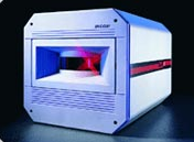
Temperature Sensor:
Contains the scanning motor & motor control, remote focusing optics, detector signal amplifier, temperature reference and controller along with non-volatile memory and optional laser alignment system. Sensor requires only one cable connection, (Power Supply/Processor cable). Each sensor requires a power Supply/Processor.
Processor/Power Supply:
Can be remotely located up to 500 or 1000-ft. from Temperature Sensor. Houses Sensor power supply, and temperature processing. Includes system and ambient alarm relays. Houses optional analog outputs and process alarm relays. Includes RS-485 digital communications, and Ethernet link for network to PC and other Sensors.
Operator Interface PC:
Operator Interface software and Operator interface PC are required to configure the Temperature Sensor and Power supply/Processor. One PC can configure up to ten Sensors on a single network. One PC can display Images for two Sensors simultaneously. One PC can save Images and Temperature Data for two or more Sensors simultaneously. With a TCP/IP Connection, the PC running a Socket Server application can provide temperature data via an ActiveX® control client, running on a 32 bit Microsoft platforms (Windows NT® 4.0 and greater and Windows 2000).
|
 Mr. Văn Tú


 pricing@stc-vietnam.com
 0916869426