Mod. MB Cylinders Aignep - Aignep Vietnam - STC Vietnam
Nhà cung cấp: STC VietNam
 Mr. Văn Tú
Mod. MB

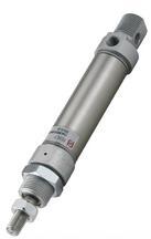
The cylinders included in this range, manufactured in conformity with the Standards DIN ISO 6432 can be used in any industrial fields. The high sliding characteristics guarantee the maximum productivity of the system. By using a special assembling operation called "double rolling" to join the end covers to the barrel, functionality and resistance are ensured.
Available versions:
Functioning: Single and Double-acting cushioned, Single or through piston rod
Bores: 8, 10, 12, 16, 20 and 25
Strokes: From 10 to 320 mm
On request: FKM seals
 |
Component Parts and Materials
1 Zinc-plated steel Nut |
|||||||||||||||||||||||||||||||||||||||||||||||||||||||||||||||||||||||||||||||||||||||||||||||||||||||||||||||||||||||||||||||||||||||||||||||||||||||||||||||||||||||||||||||||||||||||||||||||||||||||||||||||||||
| Temperatures |
Minimum temperature: 0°C (-20°C with dry air) Maximum temperature:+80°C |
|||||||||||||||||||||||||||||||||||||||||||||||||||||||||||||||||||||||||||||||||||||||||||||||||||||||||||||||||||||||||||||||||||||||||||||||||||||||||||||||||||||||||||||||||||||||||||||||||||||||||||||||||||||
| Pressures |
Minimum pressure: 1 bar Maximum pressure: 10 bar |
|||||||||||||||||||||||||||||||||||||||||||||||||||||||||||||||||||||||||||||||||||||||||||||||||||||||||||||||||||||||||||||||||||||||||||||||||||||||||||||||||||||||||||||||||||||||||||||||||||||||||||||||||||||
| Fluids | Filtered and lubricated compressed air as well as non lubricated air | |||||||||||||||||||||||||||||||||||||||||||||||||||||||||||||||||||||||||||||||||||||||||||||||||||||||||||||||||||||||||||||||||||||||||||||||||||||||||||||||||||||||||||||||||||||||||||||||||||||||||||||||||||||
|
||||||||||||||||||||||||||||||||||||||||||||||||||||||||||||||||||||||||||||||||||||||||||||||||||||||||||||||||||||||||||||||||||||||||||||||||||||||||||||||||||||||||||||||||||||||||||||||||||||||||||||||||||||||
|
||||||||||||||||||||||||||||||||||||||||||||||||||||||||||||||||||||||||||||||||||||||||||||||||||||||||||||||||||||||||||||||||||||||||||||||||||||||||||||||||||||||||||||||||||||||||||||||||||||||||||||||||||||||
|
||||||||||||||||||||||||||||||||||||||||||||||||||||||||||||||||||||||||||||||||||||||||||||||||||||||||||||||||||||||||||||||||||||||||||||||||||||||||||||||||||||||||||||||||||||||||||||||||||||||||||||||||||||||
Aignep Vietnam - STC Vietnam