Mod. XH Cylinders Aignep - Aignep Vietnam - STC Vietnam
Nhà cung cấp: STC VietNam
 Mr. Văn Tú
Mod. XH

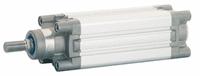
These cylinders have been manufactured in conformity with Standards ISO 15552.
The main characteristic of these cylinders is the solidity, thanks to the particular manufacturing structure they satisfy the maximum needs in terms of sliding performances and admitted loads.
They are supplied with adjustable cushioning, which is produced inside of the cover ends.
Available versions:
Functioning: Double-acting cushioned magnetic, Single-acting magnetic, Single or through piston rod magnetic, Tandem.
Bores: From 32 to 125 mm
Strokes: Standard Strokes from 25 to 1000 mm; Stroke on demand from 1000 to 2700 mm.
 |
Component Parts and Materials
1 Chrome steel C40 piston rod
If required FKM Seals |
||||||||||||||||||||||||||||||||||||||||||||||||||||||||||||||||||||||||||||||||||||||||||||||||||||||||||||||||||||||||||||||||||||||||||||||||||||||||||||||||||||||||||||||||||||||||||||||||||||||||||||||||||||||||||||||||||||||||||
| Temperatures |
Minimum temperature: 0°C (-20°C with dry air) Maximum temperature:+80°C |
||||||||||||||||||||||||||||||||||||||||||||||||||||||||||||||||||||||||||||||||||||||||||||||||||||||||||||||||||||||||||||||||||||||||||||||||||||||||||||||||||||||||||||||||||||||||||||||||||||||||||||||||||||||||||||||||||||||||||
| Pressures |
Minimum pressure: 1 bar Maximum pressure: 10 bar |
||||||||||||||||||||||||||||||||||||||||||||||||||||||||||||||||||||||||||||||||||||||||||||||||||||||||||||||||||||||||||||||||||||||||||||||||||||||||||||||||||||||||||||||||||||||||||||||||||||||||||||||||||||||||||||||||||||||||||
| Fluids | Filtered and lubricated compressed air as well as non lubricated air. | ||||||||||||||||||||||||||||||||||||||||||||||||||||||||||||||||||||||||||||||||||||||||||||||||||||||||||||||||||||||||||||||||||||||||||||||||||||||||||||||||||||||||||||||||||||||||||||||||||||||||||||||||||||||||||||||||||||||||||
|
|||||||||||||||||||||||||||||||||||||||||||||||||||||||||||||||||||||||||||||||||||||||||||||||||||||||||||||||||||||||||||||||||||||||||||||||||||||||||||||||||||||||||||||||||||||||||||||||||||||||||||||||||||||||||||||||||||||||||||
|
|||||||||||||||||||||||||||||||||||||||||||||||||||||||||||||||||||||||||||||||||||||||||||||||||||||||||||||||||||||||||||||||||||||||||||||||||||||||||||||||||||||||||||||||||||||||||||||||||||||||||||||||||||||||||||||||||||||||||||
|
|||||||||||||||||||||||||||||||||||||||||||||||||||||||||||||||||||||||||||||||||||||||||||||||||||||||||||||||||||||||||||||||||||||||||||||||||||||||||||||||||||||||||||||||||||||||||||||||||||||||||||||||||||||||||||||||||||||||||||
Aignep Vietnam - STC Vietnam