GVS 400 T10Z - OPTICAL SCALE- Thang đo quang - Givimisure Vietnam - STC Vietnam
Xuất sứ: Italy
Nhà cung cấp: STC Vietnam
Hãng sản xuất: GIVI MISURE
Ứng dụng sản phẩm: Thiết bị và hệ thống tự động hóa
 Mr Tú
Mr Tú vantu@songthanhcong.com
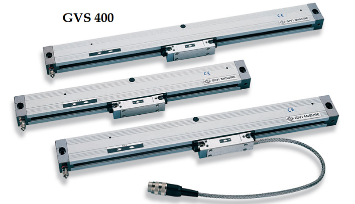
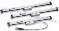
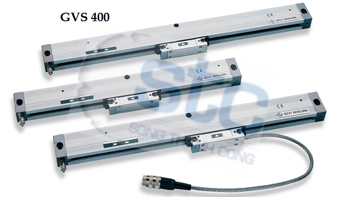
GVS 400
Thang đo quang học gia tăng cho các ứng dụng khác nhau
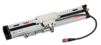
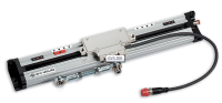
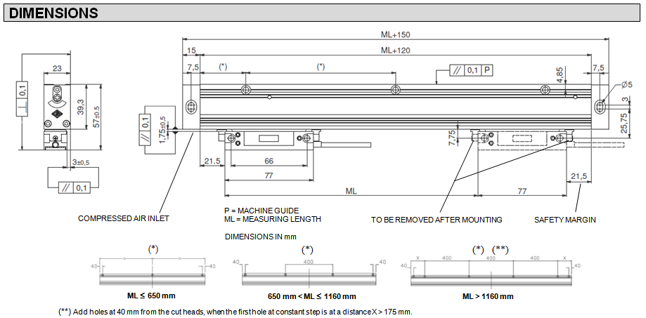
- Kích thước tổng thể nhỏ. Cấu hình chắc chắn và nặng với mặt cắt ngang rộng. Kích thước 39 × 23 mm.
- Độ phân giải lên đến 0,1 μm. Cấp chính xác ± 5 μm.
- Bốn môi niêm phong được làm bằng chất đàn hồi đặc biệt chống dầu và mài mòn, để bảo vệ tuyệt vời cho lưới.
- Trong phiên bản mô-đun để đo chiều dài trên 6.500 mm hoặc cho chiều dài đo thấp hơn theo yêu cầu.
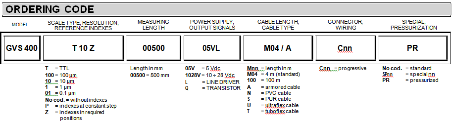
- Các chỉ mục tham chiếu ở bước không đổi, ở vị trí trung tâm hoặc ở các vị trí khác nhau theo yêu cầu.
- Dung sai căn chỉnh rộng.
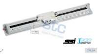
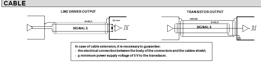
- Độ ổn định cao của tín hiệu LINE DRIVER.
- Cáp kết nối bọc thép không có kết nối bên ngoài. Đầu nối bên trong đầu dò.
- Hệ số giãn nở nhiệt tuyến tính λ = 10,6 x 10 -6 ° C -1 phù hợp với ứng dụng.
- Có đầy đủ khả năng để tháo rời và lắp ráp lại cân.
- Được bảo vệ chống đảo ngược cực của nguồn điện và ngắn mạch trên các cổng đầu ra.
|
Signal amplitude is referred to a differential measurement made with 120 W impedance and power supply voltage to the transducer of 5 V ± 5%. |
|
|
MECHANICAL AND ELECTRICAL CHARACTERISTICS
|
|||||||||||||||||||||||||||||||||||||||||
|
MECHANICAL
self-correction of mechanical hysteresis. Backlash error <0.2 μm.
ELECTRICAL
PVC, PUR, ultraflex or tuboflex cables available on request. PUR cable is suitable for continuous movements, respecting a minimum bending radius of 80 mm.
|
|
Cod. GVS 400 |
T |
||||||||||||||||||||||||||||||||||||||
|
Measuring support
Linear thermal expansion coefficient |
stainless steel grating
10.6 x 10⁻⁶ °C-1 |
||||||||||||||||||||||||||||||||||||||||
|
Reference indexes (I0) |
No cod. = without reference indexes P = constant step (every 30 mm) Z = in required positions |
||||||||||||||||||||||||||||||||||||||||
|
Resolution (µm) |
100 |
50 |
10 |
5 |
2 |
1 |
0.5 |
0.2 |
0.1 |
||||||||||||||||||||||||||||||||
|
Max. traversing speed (m/min) LINE DRIVER (VL) output |
120 |
60 |
30 |
||||||||||||||||||||||||||||||||||||||
|
Max. traversing speed (m/min) TRANSISTOR (VQ) output |
120 |
80 |
40 |
16 |
8 |
4 |
NA |
NA |
|||||||||||||||||||||||||||||||||
|
Accuracy grade |
± 5 μm * |
||||||||||||||||||||||||||||||||||||||||
|
Measuring length ML in mm |
in modular version for measuring lengths over 6500 mm or for lower measuring lengths on request |
||||||||||||||||||||||||||||||||||||||||
|
Max. acceleration |
30 m/s2 |
||||||||||||||||||||||||||||||||||||||||
|
Required moving force |
£ 4 N |
||||||||||||||||||||||||||||||||||||||||
|
Vibration resistance (EN 60068-2-6) |
100 m/s2 [55 ¸ 2000 Hz] |
||||||||||||||||||||||||||||||||||||||||
|
Shock resistance (EN 60068-2-27) |
150 m/s2 [11 ms] |
||||||||||||||||||||||||||||||||||||||||
|
Protection class (EN 60529) |
IP 54 standard IP 64 pressurized |
||||||||||||||||||||||||||||||||||||||||
|
Operating temperature |
0 °C ¸ 50 °C |
||||||||||||||||||||||||||||||||||||||||
|
Storage temperature |
-20 °C ¸ 70 °C |
||||||||||||||||||||||||||||||||||||||||
|
Relative humidity |
20% ¸ 80% (not condensed) |
||||||||||||||||||||||||||||||||||||||||
|
Reading block sliding |
by ball bearings ¥ |
||||||||||||||||||||||||||||||||||||||||
|
Power supply |
5 Vdc ± 5% or 10 ÷ 28 Vdc ± 5% |
||||||||||||||||||||||||||||||||||||||||
|
Current consumption |
140 mAMAX (with 5 V and R = 120 W) |
||||||||||||||||||||||||||||||||||||||||
|
A, B and I0 output signals |
LINE DRIVER TRANSISTOR |
||||||||||||||||||||||||||||||||||||||||
|
Max. cable length |
100 m (LINE DRIVER) 50 m (TRANSISTOR) |
||||||||||||||||||||||||||||||||||||||||
|
Electrical connections |
see related table |
||||||||||||||||||||||||||||||||||||||||
|
Electrical protections |
inversion of polarity and short circuits |
||||||||||||||||||||||||||||||||||||||||
|
Weight |
400 g + 1300 g/m |
||||||||||||||||||||||||||||||||||||||||
|
|
|||||||||||||||||||||||||||||||||||||||||