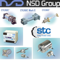
Shaded Pole Induction Geared Motor SPG Motor - SPG Motor Vietnam - STC Vietnam
Nhà cung cấp: STC VietNam
 Mr Tú
Mr Tú vantu@songthanhcong.com
CODING SYSTEM
| ■ Coding System |

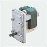
| ■ Typical Geared Motor Construction |

■ Comparison of torque characteristics (3 Core 31 Core)
| Customer should be provided the correct specification (torque and speed, operation condition) for motor required a set. According with these conditions, motor manufacturer will disign suitable input torque and gear ratio. Shaded pole motor operates with single directio by AC voltage and also is low-efficientmotor, but make a advantage of size and price area, and applied to various set. |
■ MODEL CHARACTORISTICS
|
Unit conversion : 1kgf.cm = 0.1N-m
|
|
Continuous(S1)
|
ⅰ
|
ⅱ
|
||||||||||||
|
Continuous(S1)
|
Intermittent(S2 15min)
|
|||||||||||||
|
Ts
|
Ts
|
Tb
|
Ts
|
Tr
|
Tb
|
|||||||||
|
kgf-cm
|
N-m
|
kgf-cm
|
N-m
|
kgf-cm
|
N-m
|
kgf.-cm
|
N-m
|
kgf-cm
|
N-m
|
kgf-cm
|
N-m
|
|||
|
A
|
3 Core
|
15
|
0.05
|
0.05
|
0.085
|
0.0085
|
0.10
|
0.010
|
0.10
|
0.010
|
0.170
|
0.0170
|
0.20
|
0.020
|
|
B
|
20
|
0.07
|
0.07
|
0.128
|
0.0128
|
0.15
|
0.015
|
0.15
|
0.015
|
0.255
|
0.0255
|
0.30
|
0.030
|
|
|
C
|
25
|
0.10
|
0.010
|
0.170
|
0.0170
|
0,20
|
0.020
|
0.20
|
0.020
|
0.340
|
0.0340
|
0.40
|
0.040
|
|
|
D
|
30
|
0.12
|
0.012
|
0.213
|
0.0213
|
0.25
|
0.025
|
0.25
|
0.025
|
0.425
|
0.0425
|
0.50
|
0.050
|
|
|
E
|
40
|
0.15
|
0.015
|
0.298
|
0.0298
|
0.35
|
0.035
|
0.30
|
0.030
|
0.595
|
0.0595
|
0.70
|
0.070
|
|
|
F
|
50
|
0.20
|
0.020
|
0.383
|
0.0383
|
0.45
|
0.045
|
0.40
|
0.040
|
0.680
|
0.0680
|
0.80
|
0.080
|
|
|
G
|
31 Core
|
15
|
0.15
|
0.015
|
0.038
|
0.0038
|
0.15
|
0.015
|
0.30
|
0.030
|
0.075
|
0.0075
|
0.30
|
0.030
|
|
H
|
20
|
0.20
|
0.020
|
0.050
|
0.0050
|
0.20
|
0.020
|
0.40
|
0.040
|
0.100
|
0.0100
|
0.40
|
0.040
|
|
|
I
|
25
|
0.25
|
0.025
|
0.063
|
0.0063
|
0.25
|
0.025
|
0.50
|
0.050
|
0.125
|
0.0125
|
0.50
|
0.050
|
|
|
J
|
30
|
0.30
|
0.030
|
0.075
|
0.0075
|
0.30
|
0.030
|
0.60
|
0.060
|
0.150
|
0.0150
|
0.60
|
0.060
|
|
■ N-T CURVE CHARACTORISTICS
 |
 |
Note)
1. Tb: Break Down Torque. Ts: Starting Torque, Tr: Rating Torque (About Max Effeciency)
2. Geared Motor Output Torque = Motor Torque X Gear Ratio X Gears Step(90%)
Ex) Motors(C-i) + Gear Ratio(1/192) = 0.01 X 192 X 0.9^3 = 1.3999 N-m(Ts)
3. Motor specification Data may be largely differed according with Duty Type and Cooling methods.
4. If fan installed. Motor output canbe increased approximately 20%.
5. Reter to Motor Specification Data above. (Contact with agency or RD for development)
6. Geared Motor Torque can be used within maximum permissible torque of GearBox. (Reter to &'Maximum Permissible Torque
of Gear Box&' table)
|
|
| 2. CHARACTERISTICS |
■ Torque Conversion Chart
|
|
Ib-ft
|
Ib-in
|
oz-in
|
Dyne-cm
|
Nm
|
Ncm
|
Kpm(kgfm)
|
gcm
|
|
Ib-ft
|
1
|
12
|
192
|
1.356 X 10⁷
|
1.356
|
1.356 X 10²
|
0.1383
|
1.356 X 10⁴
|
|
Ib-in
|
8.333 X 10⁻²
|
1
|
16
|
1.1298 X 10⁶
|
0.113
|
11.3
|
1.1152 X 10⁻²
|
1.152 X 10³
|
|
oz-in
|
5.208 X 10⁻³
|
6.250 X 10⁻²
|
1
|
7.062 X 10⁴
|
7.062 X 10⁻³
|
0.7062
|
7.201 X 10⁻⁴
|
72.01
|
|
Dyne-cm
|
7.376 X 10⁻⁴
|
8.851 X 10⁻⁷
|
1.416 X 10⁻⁵
|
1
|
10-7
|
10-5
|
1.0197 X 10⁻⁸
|
1.0197 X 10⁻³
|
|
Nm
|
0.7376
|
8,8509
|
1.4161 X 10⁻²
|
107
|
1
|
102
|
0.10197
|
1.0197 X 10⁴
|
|
Ncm
|
7.376 X 10⁻³
|
8,8509 X 10⁻²
|
1.4161
|
105
|
10-2
|
1
|
1.0197 X 10⁻³
|
0.10197
|
|
kpm(kgfm)
|
7.233
|
86.79
|
1.389 X 10³
|
9.8067 X 10⁷
|
9.8066
|
980.665
|
1
|
105
|
|
gcm
|
7.233 X 10⁻⁵
|
8.680 X 10⁻⁴
|
1.389 X 10⁻² |
980.67
|
9.8066 X 10⁻⁵
|
9.8066 X 10⁻³
|
10-5
|
1
|
| ■ How to Select a Geared Motor | |
|
ELECTRICAL CONSIDERATION Determine the nominal or rated voltage and frequency. Also, the high and low voltage conditions must be addressed, as there is a direct relationship between voltage, motor performance and winding temperature. |
|
|
TORQUE Torque performance is normally rated in newton meters (or inch-punds) of starting, running, or breakdown torque. It is important to determine if the torque load is immediate, gradual, or of shock nature. This decision is essential for determination of the proper motor, gearing and gearcase configuration. All variable loads and worst case scenarios of your application must be considered. |
|
■ Maximum permissdible Torque of Gear Box

■ Gear Box Motor Combinations
|
TYPE
|
SG
|
SG2
|
SQ
|
SVO
|
SV
|
SV-1
|
SZ
|
SP
|
SK
|
D
|
F
|
|
31 Core
|
|
●
|
●
|
●
|
|
|
●
|
●
|
|
|
|
|
3 Core
|
●
|
●
|
●
|
●
|
●
|
●
|
●
|
●
|
●
|
●
|
●
|
|
FAN ASS&'Y
|
●
|
●
|
●
|
●
|
●
|
●
|
●
|
●
|
●
|
●
|
●
|
|
CLUTHCH BRAKE
|
●
|
●
|
●
|
●
|
●
|
●
|
●
|
●
|
●
|
●
|
●
|
※ Mounting of cluthch brake can apply the ISG-3 TYPE only.(CORE STACK 25 Min.)
TORQUE MEASUREMENT
There are two commonly used methods of measuring torque if you are unsure of your torque requirements:
① String and Pulley Method
|
Affix a pulley to the shaft of the machine to be dirven (see fig. A). Secure one end of a cord to the outer surface of the pulley and wrap the cord around it a number of times. Tie the other end of the cord to a spring scale. Pull on the scale until the shoft turns. The force, in pounds indicated on the scale, multiplied by the radius of the pulley gives the torque of twisting rate in kgf-cm. Depending on the application, and if used carefully, this method is reliable in determining both starting and running torque. When the pulley begins to turn, starting torque is indicated. The average running torque can be determined it a long enough string is used. When the torque characteristics of the machine vary in different parts of the operating cycle, the starting torque must be determined at the point where the motor or Geared Motor will "see" highest resistance (torque) to starting. |
■ Simple "string and pulley" method of torque measurement
(Torque = Force reading on spring scale x radius of the pulley)
② Wrench Mehod
| A simple torque wrench can be applied to the shaft of the machine to be driven. Turn the wrench as you would an ordinary pipe wrench and, when the shaft begins to rotate, read the value (kgf-cm) on the torque wrench gauge. The observed value represents the torque required to start the machine. This method is normally limited to obtaining starting torque or peak torque values, as it is unsafe and difficult to attempt to continuously rotate a torque wrench. |
|

OUTPUT SPEED
Speed (RPM) is rated in a full load or free running condition. The rated frequency. If applicable, of the associated voltage will
affect overall output speed. The performance of the Geared Motor can be effected with the use of dual frequency AC coils.

ENVIRONMENT
Environmental areas of cercern should be storage, condition when not running and maximum usage. Numerous applications involve caustic, dusty, humid or exterme temperature environments. Please consider all conditions within the specific environment.
DUTY CYCLE
This specification is critical in determining the endurance of the gearmotor as it relates to the total product and application.
The most important criteria are "time-on" and "time-off" in actual seconds, minutes, or hours. Also important is the total
number of cycles when considering Geared Motor design.
FORCES ON SHAFT
An extensive radial load may dictate a larger shaft diameter for increased bearing surface. Extreme condition(s) may dictate
needle bearings. Light axial loads require the use of appropriate thrust washers. The Geared Motor output shaft may not support excessive axial loads.
SHAFT ROTATIOS, DIMENSIONS AND MACHINNING
Shaft Rotations must be considered carefully expecially when reversing motors are being used. Reversibility is more costly and involoves additional circuitry. With uni-directional gearmotors the direction of rotation is specified from the shaft end of a single shaft gearmotor. With dual shaft gearmotors, the direction of rotation is specified from either the cover of the gearcase or the motor side of the gearcase. Output shaft diameter, length and machining should be determined with the advice
of your SPG. CO. Ltd Sales team.
MOTOR PROTECTION
From a mechanical standpoint, first determine it a stalled condition is a normal mode of operation, occasional or unintentional.
Gearcase and motor designs are greatly influenced by this criteria. There are two basic types of recognized locked rotor AC
motor protection, recongnized by the U.L and C.S.A.
① Thermal Protection
Utilizes a thermal protector located on the motor coil. Should a coil reach a maximum temperature as prescribed in agency
standards (Class A, Class B, etc.) the thermal protector will open, shutting off current to the motor winding.
Tripping of the thermal protector should be condisered unusual.
② Impedance Protection
This type relies on the inherent total impedance of the stator/coil combination to dissipate excessive winding temperatures.
MOUNTING STYLE AND POSITION
Design condiderations will be effected by the position of the Geared Motor in the application. The mounting position may affect shaft loading or the performance of the optional motor brakes. The optimal position for peak performance is a horizontal shaft-mounting configuration.
|
|
| 3. TECHINICAL ADVICE |
■ Glossary of Terms
| → | Ambient | The temperature and the humidity of the surrounding while operating. Generally, the motor is designed to operate in the condition of the surrounding temperature from -10℃~40℃ (14℉~104℉) and the surrounding humidity below 80% (no dew condensation). |
| → | Overheating Protection | When motor operates, due to the overload or the input current, the temperature of the motor rises. So in order to prevent overheating, the motor includes built-in automatic-return type T/P (thermal protector). The T/P disconnects the power when the temperature rises and reconnects when the motor cools down automatically. |
| → | Thermal Protector | The device which automatically disconnects the power of the motor when there is abrupt temperature rise due to overload or other operation detect. |
| → | Torque | The tendency of a force to rotate an object about an axis, fulcrum or pivot. |
| → | Starting Torque | The torque that the motor develop when it starts at zero speed. |
| → | Stall Torque(=Breakdown Torque) | The maximum torque of the operating motor. The torque increases more than the stall torque, the motor stops or the speed changes. |
| → |
Rated Torque |
The torque of the motor at the rated speed (rpm). |
| → | Braking | The mechanical and/or electrical mechanism that reduces or stops instantly or reduces the speed to control the overrun. The degree of holdig torque will change as the selected brake type. |
| → | Coupling Load to Shaft | Consider the form of the coupling with the configuration and machining of the output shaft. The superlative design is to locate the load nearest to the gear-case output bearing. |
| → | Duty Cycle | The cycles between operation and stop. |
| → | Full Load | The minimum speed of the induction motor operated under rated load output torque. Full load changes by the rating and characteristics of the specific motor and is less than the synchronous speed. |
| → | Full Load Current | The current generated by the motor operated at the rated output torque and the voltage. |
| → | Hertz(Hz) | Frequency of AC power in cycles per second. Generally in Korea, it is 60Hz, but the overseas, it changes. |
| → | Impedance Protected | Under Locked rotor or stalled condition, motor is thermally protected from the motor impedance to prevent burnout per UL standard No. 1004-2. |
| → | Motor Type | Classitication of the motor under its&' characteristics and power specified. For example, 3 type or 31 type of shaded core. |
| → | Mounting | The position of the mounting may affect the shaft loading and performance of the optional motor brake. |
| → | Output Speed | Speed rated as revolution per minute in a full load or free operation confition. The rated frequency of the voltage affects the overall output speed. |
| → | Overhung Load | The load on the motor or gearhead output shaft in the radial direction. The bearing and the shaft must support this load while transmitting power. |
| → | Rotation | Direction of the shaft rotating in clockwise (CW), counterclockwise (CCW) or reversing. |
| → | Shaded Pole |
The economical motor consisting of steel laminations, electrical field coil, small copper shading coil and the rotor. SPG provides high starting and high running torque models. |
| → | Sleeve Bearing | Used when low noise level is required. Can be mounted in any position, shaft-up, down, left and right. |
| → | Temperature Rise | The temperature above the surrounding when the motor is operating. |
| → | Alternating Current | The movement of electric chanrge periodically reverses direction. |
| → | Direct Current | The unidirectional flow of electric charge. |
SPG Motor Vietnam - STC Vietnam